
Abstract
Solid-state thermal management has become indispensable across industries where vibration-free, precise temperature regulation is critical. This guide examines the fundamental physics, design considerations, application landscape, and operational best practices for Thermoelectric Coolers. From the reversible Peltier effect to real-world deployment in fiber optics, medical diagnostics, and automotive sensing, the following sections provide engineers and technical decision-makers with actionable knowledge for selecting, integrating, and maintaining these devices in demanding environments.
Table of Contents
- Understanding the Peltier Effect and TEC Architecture
- Key Specifications and Module Selection Criteria
- Maximizing Cooling Efficiency in Practical Designs
- Industrial and Medical Application Landscape
- Installation, Drive, and Environmental Protection
- Maintenance, Lifespan, and Failure Prevention
- Frequently Asked Questions
Understanding the Peltier Effect and TEC Architecture
The operating foundation of every Thermoelectric Coolers device rests on a phenomenon discovered by Jean Charles Athanase Peltier in 1834. When direct current passes through a junction formed by two dissimilar semiconductor materials, one junction absorbs heat while the other releases it. This reversible thermal transfer — known as the Peltier effect — enables a single module to function as either a cooler or a heater simply by reversing the polarity of the input current.
Cold Junction and Hot Junction Behavior
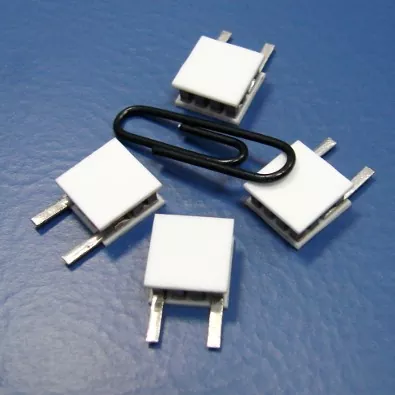
Inside a typical Peltier module, dozens to hundreds of p-type and n-type semiconductor pellets are arranged electrically in series and thermally in parallel. The pellets are sandwiched between two ceramic substrates that conduct heat while providing electrical insulation. When DC current flows from the n-type to the p-type material, the junction absorbs heat, creating a cold side. Current flowing from p-type to n-type releases heat, forming the hot side.
This architecture produces a temperature differential across the module that can be precisely modulated by adjusting the current magnitude. The absence of compressors, refrigerants, and moving parts distinguishes this technology from conventional vapor-compression systems, offering advantages in reliability, noise profile, and form-factor flexibility.
Materials and Construction
Bismuth telluride (Bi₂Te₃) remains the most efficient thermoelectric material for near-room-temperature operation. The semiconductor pellets are soldered between ceramic plates typically made from alumina (Al₂O₃) or aluminum nitride (AlN). Metal interconnects join the individual pellets into a continuous circuit, and the completed assembly is often no larger than a few square millimeters to a few square centimeters depending on cooling capacity requirements.
Key Specifications and Module Selection Criteria
Selecting the appropriate module requires careful evaluation of thermal load, target temperature differential, available space, and power budget. Datasheet parameters alone do not guarantee optimal performance — engineers must model the operating point against real-world conditions.
Critical Datasheet Parameters
Four parameters form the backbone of any selection decision. The maximum cooling capacity (Q_max) represents the heat pumping capability at zero temperature differential. The maximum temperature differential (ΔT_max) indicates the largest achievable temperature span between hot and cold sides under zero heat load. Maximum current (I_max) and maximum voltage (V_max) define the electrical operating envelope.
Crucially, Q_max, ΔT_max, and I_max cannot be achieved simultaneously. Operating the module near any single maximum forces the other two parameters to decline. Selection must therefore be based on normalized performance curves that describe behavior at the actual target operating point.
Application-Driven Selection Guidance
| Application Condition | Recommended Direction |
|---|---|
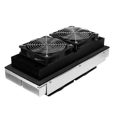
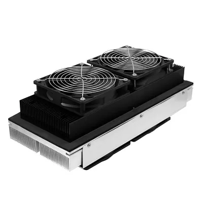
| Small footprint, low heat load | Air-cooled TEC assembly |
| Space-constrained enclosure | Liquid-cooled TEC configuration |
| Continuous liquid temperature regulation | Liquid-to-liquid TEC platform |
| High heat load density | Enhanced hot-side dissipation with recalculated operating point |
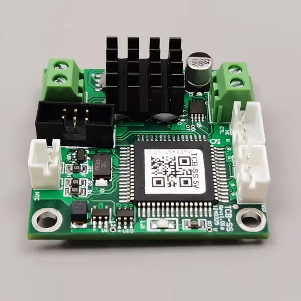
| Sub-0.1°C precision requirement | TEC with sensor feedback and PID controller |
| Bidirectional heating and cooling | H-bridge-driven two-way temperature control |
Maximizing Cooling Efficiency in Practical Designs
Coefficient of performance (COP) for single-stage thermoelectric modules typically falls between 0.3 and 0.7, though well-optimized systems can exceed this range when the temperature differential is modest. Poorly designed implementations frequently drop below 0.2. The gap between these outcomes depends on three design levers.
Sizing Strategy: Deliberate Oversizing
Perhaps the most counterintuitive yet impactful practice involves selecting a module with a maximum cooling capacity four to six times the actual heat load, then operating it at only 20–35% of maximum current. This approach minimizes Joule heating losses, which grow with the square of current, while still delivering the required heat pumping. The module runs cooler, lasts longer, and consumes less power for the same thermal task.
Hot-Side Heat Rejection
The hot side of a Peltier module must reject not only the pumped heat load but also the electrical input power itself. Total heat rejection equals the cooling load plus the electrical power consumed. Undersizing the hot-side heatsink forces the cold side to work against an elevated ambient, eroding performance and accelerating degradation. Liquid cooling or high-efficiency forced-air heatsinks are often necessary when heat loads exceed a few watts.
Control Strategy
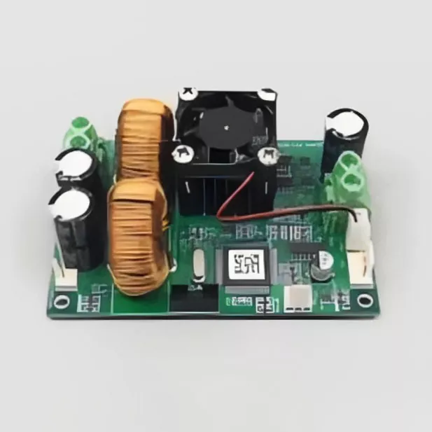
A precision PID controller paired with a high-resolution temperature sensor enables set-point stability within ±0.1°C or better. The controller modulates current to the module rather than switching it fully on and off, avoiding thermal cycling stress and improving steady-state stability.
Industrial and Medical Application Landscape
The unique combination of solid-state operation, millisecond response, and sub-ambient cooling capability has driven adoption across a remarkably diverse set of industries. Each application leverages a different subset of advantages offered by Thermoelectric Coolers.
Fiber Optic Communication and Photonics
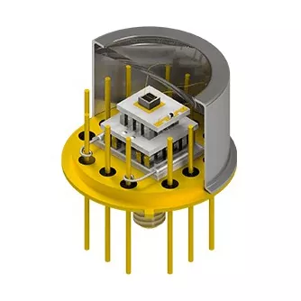
Optical transceivers, laser diodes, and pump lasers require wavelength stability that is directly tied to junction temperature. A shift of even a fraction of a degree can cause wavelength drift beyond specification limits. Thermoelectric modules maintain laser temperature within ±0.1°C, ensuring stable output across ambient fluctuations.
Medical Diagnostics and Life Sciences
Polymerase chain reaction (PCR) instruments depend on rapid, precise thermal cycling between denaturation, annealing, and extension temperatures. Peltier-driven thermocyclers achieve heating rates exceeding 20°C per second and cooling rates above 5°C per second, enabling faster diagnostic turnaround. Temperature uniformity across a 96-well plate can be maintained within ±0.1°C.
Medical laser systems — including CO₂, YAG, diode, and fiber lasers — rely on thermoelectric stabilization to protect optical components and maintain beam quality. The solid-state nature of TECs allows integration into compact handpieces and console-mounted laser heads without the vibration that would disturb optical alignment.
Automotive Sensing and LiDAR
Automotive LiDAR systems use laser diodes whose emission wavelength shifts with temperature. TECs stabilize these laser sources against extreme under-hood temperature swings, preserving detection accuracy and range performance. The absence of moving parts is particularly valuable in high-vibration automotive environments.
Industrial Instrumentation and Analytical Equipment
Analytical instruments, semiconductor fabrication equipment, and environmental analyzers use thermoelectric temperature control for sample conditioning, detector cooling, and reference-point stabilization. Cold plates and liquid-to-liquid assemblies provide the thermal stability required for repeatable measurements in process control environments.
Installation, Drive, and Environmental Protection
Proper installation and electrical drive are essential for achieving rated performance and ensuring module longevity. Many premature failures stem from avoidable assembly and operating errors rather than inherent product limitations.
Mounting and Thermal Interface
Contact surface flatness between the module, heatsink, and cold plate should be better than ±0.02 mm. A thin, uniform layer of high-quality thermal grease — approximately 0.02 mm to 0.1 mm thick — must be applied to both the hot and cold faces to minimize contact thermal resistance.
Screws should be tightened diagonally in stages. The recommended compression ranges from 150 to 300 kPa (approximately 10 to 21 kg/cm²). Excessive or uneven pressure can fracture the brittle ceramic substrate and damage internal semiconductor pellets.
Power Supply Requirements
A DC regulated power supply with less than 10% ripple is mandatory. Constant-current drive or PWM voltage regulation is preferred over direct full-voltage hard starting, which can stress the module and reduce operational life. When switching between heating and cooling modes, reverse polarity must only be applied after the module has returned to room temperature — typically after a 10 to 15 minute cooldown period.
Condensation and Environmental Protection
Operation below ambient dew point will cause condensation on the cold side. Moisture ingress can degrade thermal performance and corrode internal connections over time. Protective measures include thermal insulation wrapping, potting compound sealing, hydrophobic coatings, and designed drainage channels. Use in corrosive gas environments should be avoided unless the module is fully encapsulated.
Maintenance, Lifespan, and Failure Prevention
Thermoelectric coolers are inherently reliable devices with mean time between failures frequently cited in the range of 100,000 to 200,000 hours under favorable conditions. However, actual lifespan depends heavily on thermal cycling amplitude, current drive profile, and environmental factors.
Routine Inspection Practices
- Inspect thermal grease condition every six months; reapply if drying or cracking is observed.
- Clean hot-side heatsink fins with compressed air to maintain airflow and heat rejection capability.
- Verify temperature stability during operation — increasing fluctuation may indicate degrading thermal interface or module fatigue.
- Monitor current draw at the operating point; rising current for the same thermal load suggests increasing internal resistance.
Common Failure Modes
Thermal stress from repeated cycling between hot and cold states remains the dominant degradation mechanism. Solder joint fatigue and semiconductor pellet cracking can develop after hundreds of thousands of cycles if the temperature swing is large. Operating the module at lower current fractions and maintaining stable thermal interfaces significantly extends service life.
Moisture-related failures — including corrosion and electrical shorting — are preventable through proper sealing and condensation management. In applications where the cold side operates below dew point, robust moisture protection is not optional but essential for reliable long-term operation.
Frequently Asked Questions
Can a thermoelectric cooler simultaneously cool and heat?
Yes. By controlling the H-bridge circuit to change the polarity of the input DC power, the cold and hot side functions can be switched within milliseconds. This enables bidirectional precise temperature control without an additional heating element. A single module can cool a component during operation and warm it during startup or idle periods.
What are the key process details when installing a thermoelectric cooler?
Three factors are critical. First, contact surface flatness between the heatsink and cold plate should be better than ±0.02 mm. Second, a thin, uniform layer of high thermal conductivity silicone grease must be applied to both sides. Third, screws must be tightened diagonally and evenly, with recommended pressure between 150 and 300 kPa. Uneven force can crush the internal semiconductor pellets and destroy the module.
Do thermoelectric coolers meet international environmental standards?
Yes. Thermoelectric coolers use no chlorofluorocarbons (CFCs), hydrochlorofluorocarbons (HCFCs), or other chemical refrigerants throughout their entire lifecycle. They naturally comply with the most stringent environmental regulations, including European RoHS and REACH directives as well as North American environmental requirements.
What happens if the current direction is reversed during operation?
The cold and hot sides swap — the module begins heating on what was previously the cold face. This is a normal and useful feature for bidirectional temperature control. However, reverse polarity should only be applied after the module has returned to near room temperature. Instantaneous reversal under load can cause thermal stress that damages solder joints and semiconductor pellets.
Can thermoelectric coolers operate in a vacuum?
Yes. Thermoelectric coolers are compatible with vacuum environments because their construction uses no organic materials that would outgas. The one restriction is lead insulation — PVC-insulated wires should be avoided. Teflon-insulated or uninsulated wire leads are preferred for vacuum applications.
How low can a thermoelectric cooler go in temperature?
A single-stage module can typically achieve a temperature differential of 60 to 70°C between the hot and cold sides. Using multi-stage cascaded modules in a vacuum environment, temperatures as low as −100°C are achievable. However, each additional stage reduces overall COP, so multi-stage designs are reserved for applications where the temperature target justifies the efficiency penalty.
Every thermal challenge has a solid-state solution waiting to be engineered. Whether the requirement calls for sub-ambient cooling of a laser diode, precise temperature cycling for molecular diagnostics, or robust thermal stabilization in an automotive sensor package, the right module configuration and drive strategy make the difference between adequate and exceptional performance.
Contact Us to Discuss Your Thermal Management Requirements