X-Meritan manufactures NTC Thermistor for Optical Communication used for temperature sensing in optical transceivers, including SFP, QSFP, and CFP form factors. These components are placed close to the laser diode or inside the TEC control loop to provide real-time temperature feedback. The resistance value changes predictably with temperature, allowing the control circuit to maintain a stable laser operating point.
Accurate temperature monitoring in optical modules is not a convenience feature. Laser wavelength shifts by approximately 0.1 nm per degree Celsius for many DFB lasers. A temperature drift of a few degrees can move the output outside the acceptable channel window in DWDM systems. The NTC Thermistor for Optical Communication provides the feedback signal that the TEC driver uses to correct this drift.
The NTC Thermistor for Optical Communication is typically bonded to the same submount as the laser diode or attached to the TEC cold side. As the laser temperature changes, the thermistor resistance changes according to a nonlinear curve defined by the R25 value and the B constant. The control circuit measures this resistance, converts it to a temperature value, and adjusts the TEC current to bring the laser back to the target temperature.
The relationship between resistance and temperature follows the standard equation:
R(T) = R25 × exp[ B × (1/T - 1/298.15) ]
Where T is in Kelvin and B is the material constant. For optical module applications, B25/50 values between 3380 K and 3950 K are common. The choice depends on the expected operating temperature range and the resolution required by the control circuit.
The table below lists standard configurations available from X-Meritan. Custom values are possible for volume projects.
|
Parameter |
Symbol |
Test Condition |
Standard Values / Range |
Notes |
|
Nominal resistance at 25°C |
R25 |
25°C ± 0.01°C, low power |
10 kΩ, 50 kΩ, 100 kΩ |
Other values from 1 kΩ to 500 kΩ on request |
|
Resistance tolerance |
– |
25°C |
±1%, ±3%, ±5% |
±0.5% available for selected values |
|
B value |
B25/50 |
25°C / 50°C |
3380 K, 3435 K, 3950 K |
Other B values on request |
|
B value tolerance |
– |
– |
±0.5%, ±1% |
Affects temperature accuracy at the extremes |
|
Thermal time constant |
τ |
Still air |
≤ 3 seconds |
Smaller chip sizes respond faster |
|
Dissipation factor |
δ |
Still air |
≥ 1.5 mW/°C |
Self-heating must be kept below 0.1°C |
|
Operating temperature range |
Topr |
– |
-40°C to +125°C |
Continuous operation |
|
Rated power at 25°C |
Pmax |
25°C |
10 mW |
Exceeding this causes self-heating error |
|
Insulation resistance |
RI |
500 VDC |
≥ 100 MΩ |
Between terminals and coating |
|
Withstand voltage |
– |
500 VAC, 60 s |
No breakdown |
For safety isolation |
All values are verified in production. A full test report with resistance and B value measurements can be supplied for each batch.
Important note on self-heating: The measurement current through the NTC must be low enough that the power dissipated in the thermistor does not raise its temperature by more than 0.1°C. For a 10 kΩ NTC with a dissipation factor of 1.5 mW/°C, this means the measurement current should stay below approximately 120 µA. Exceeding this causes the thermistor to read a higher temperature than the actual laser temperature, which can lead the control loop to overcool.
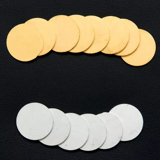
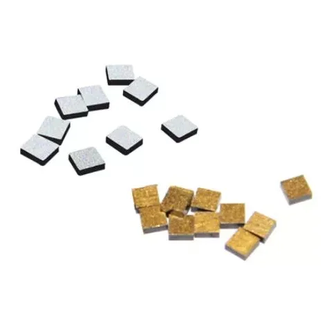
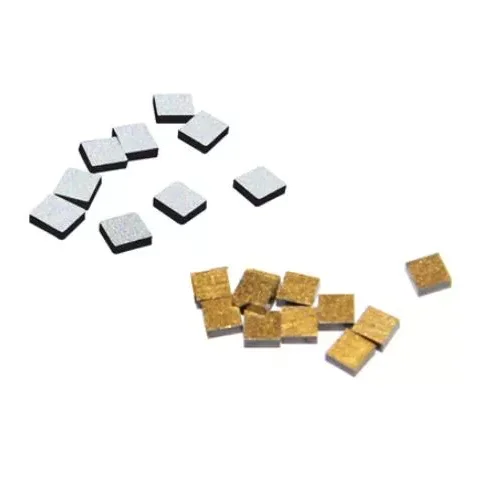
X-Meritan supplies NTC Thermistor for Optical Communication in bare chip form, with Au or Ag electrodes, suitable for wire bonding or soldering onto ceramic submounts. The chip dimensions are typically in the range of 0.5 mm × 0.5 mm to 1.0 mm × 1.0 mm, with a thickness from 0.2 mm to 0.5 mm. This small footprint allows placement directly adjacent to the laser diode without interfering with the optical path.
For customers who prefer a pre-mounted component, the chip can be assembled onto a small alumina or aluminum nitride carrier with lead wires. This version is easier to handle in manual assembly lines and simplifies the bonding process.
The electrode surface is designed for either Au wire bonding or PbSn/AuSn soldering. The specific metallization is selected based on the customer's assembly process. We provide datasheets with the recommended bonding parameters for each electrode type.
The thermal time constant of a bare chip NTC is typically below 1 second when mounted with a thin layer of thermal adhesive or solder. In still air, without mounting, the time constant is higher. For optical module applications, the NTC must be thermally coupled to the same surface as the laser diode or TEC cold plate. A thick glue line or air gap will slow the response and introduce a temperature offset between the sensor and the laser.
We recommend mounting the NTC chip with a thermally conductive adhesive or solder preform. The thickness of the bonding layer should be controlled to less than 25 µm. This ensures that the NTC tracks the laser temperature with minimal delay, which is critical for TEC control loops operating at update rates above 10 Hz.
NTC Thermistor for Optical Communication can exhibit small resistance drift over time, especially when operated at elevated temperatures. Our material formulation and electrode passivation reduce this drift to a level that does not affect optical module performance over a typical 10-year service life. The table below shows expected drift under different storage conditions, based on internal reliability testing.
|
Condition |
Duration |
Typical Resistance Drift |
|
125°C dry storage |
1000 hours |
< 0.5% |
|
85°C / 85% RH |
1000 hours |
< 0.8% |
|
Thermal cycling -40°C to +125°C |
500 cycles |
< 0.5% |
|
Operating life at 25°C |
10 years (estimated) |
< 1.0% |
These values are based on accelerated testing and are not guarantees. Actual drift depends on mounting stress, humidity, and operating current. We can provide a detailed reliability report for qualified projects.
The NTC chips are produced in our own facility using ceramic processing techniques. The manufacturing flow includes powder preparation, tape casting, electrode printing, sintering, dicing, and final electrical testing. We control the material composition in-house, which allows adjustment of the B value and resistance characteristics.
Each batch is tested for:
● Resistance at 25°C using a precision constant temperature bath
● B value calculated from resistance measurements at 25°C and 50°C
● Visual inspection under magnification
● Insulation resistance
● Optional thermal cycling per customer request
Test data is archived and can be made available with each shipment. We also support customer-specific incoming inspection procedures.
To select the correct NTC thermistor for your optical module, consider the following factors:
Common values are 10 kΩ and 100 kΩ. Lower resistance values draw more measurement current but are less sensitive to noise. Higher resistance values are easier to measure with simple ADC circuits. The choice often depends on the TEC controller IC used in the module. Many laser driver and TEC controller chips are optimized for a specific NTC resistance range, typically 10 kΩ or 50 kΩ.
The B value determines how much the resistance changes per degree. A higher B value gives a larger resistance change per degree, which can improve temperature resolution. However, a very high B value also means the resistance becomes very high at low temperatures, which may exceed the input range of the measurement circuit. B25/50 = 3435 K is a common compromise for optical modules operating from -10°C to +75°C.
The resistance tolerance and B value tolerance directly affect the temperature measurement accuracy. A ±1% resistance tolerance combined with ±1% B value tolerance results in an initial temperature error of approximately ±0.3°C at 25°C. For DWDM applications where wavelength stability must be within ±0.01 nm, this error may be too large. A calibration step in the module firmware can compensate for the initial tolerance, but the tolerance must be tight enough that the calibration remains valid over the operating range.
The NTC must fit within the available space inside the optical module. Bare chips offer the smallest footprint but require wire bonding or die attach equipment. Pre-mounted chips on ceramic carriers simplify assembly but add height. We can provide both options and advise on the best choice for your production line.
The measurement current must be kept low. For a 10 kΩ NTC with a dissipation factor of 1.5 mW/°C, the maximum measurement current for 0.1°C self-heating is approximately 120 µA. If your TEC controller uses a higher current, consider a lower resistance NTC or a larger chip with higher dissipation factor.
If you are unsure which parameters to choose, provide your TEC controller part number and the target temperature range. We can recommend a compatible NTC configuration.
NTC thermistors are used inside the module to monitor laser temperature. The signal feeds into the TEC controller, which maintains the laser at a fixed temperature, typically 25°C or 45°C depending on the laser design.
For narrow linewidth and wavelength-stable lasers, the NTC accuracy is critical. The control loop must hold the temperature within ±0.1°C to keep the wavelength within the specified channel grid.
In bare laser diode packages, the NTC is bonded to the same submount as the laser chip. This provides direct temperature sensing without additional thermal mass.
NTC thermistors are also used in the temperature monitoring circuits of outdoor optical amplifiers and transceivers, where ambient temperature swings can be large.
A: R25 is the resistance at 25°C. The B value describes how the resistance changes with temperature. Both parameters are needed to calculate the resistance at any other temperature. A higher B value means the resistance changes more for a given temperature change.
A: The simplest method is to use a lookup table generated from the R25 and B values using the Steinhart-Hart equation or the simplified B equation. Many TEC controller ICs have built-in conversion algorithms. We can provide the coefficient table for your specific NTC.
A: It depends on your calibration procedure. A ±5% resistance tolerance combined with ±1% B tolerance results in a temperature error of over ±1°C before calibration. If your production line performs a one-time calibration at a known temperature, the initial offset can be removed. But the B tolerance still affects the slope accuracy. For DWDM, we recommend at least ±1% resistance and ±0.5% B value.
A: Even small currents can heat the thermistor above the surrounding temperature. A 100 µA current through a 10 kΩ NTC dissipates 0.1 mW. With a dissipation factor of 1.5 mW/°C, this causes a 0.067°C temperature rise. In a tightly controlled laser module, that offset can be significant. The measurement circuit should use the lowest practical current.
A: Yes. We can adjust the material composition to achieve custom B values in the range of 3000 K to 4500 K, and we can screen for specific resistance values with tight tolerances. Minimum order quantities apply.
A: Usually not. The NTC is mounted on the submount or TEC cold side, not on the laser facet. Direct contact with the laser chip could introduce electrical issues or thermal mass problems. We recommend mounting the NTC as close as possible to the laser but electrically isolated.
To request samples or a detailed recommendation, please provide the following:
● TEC controller part number or measurement current
● Target laser temperature
● Required temperature accuracy
● Available space for the NTC
● Assembly method (wire bonding, soldering, epoxy)
● Expected annual volume
We respond within one business day and can provide samples for evaluation.
Address
Building C2, R&F Center, Shangpu Road, Taijiang District, Fuzhou City, Fujian Province, China
Tel
Ready to start your next thermal management project or request a competitive price quote? The X-meritan engineering and sales team is standing by to analyze your project requirements, recommend suitable standard TEC models, or discuss fully custom thermoelectric cooler manufacturing options.
Simply fill out the inquiry form with your operating parameters—such as heat load, ambient temperature, target cold-side temperature, dimensions, and estimated annual volume. Our technical sales engineers will review your thermal constraints and respond with a detailed quotation and engineering assessment within 24 business hours.