News

How Can Engineers Calculate the Required Cooling Load Before Choosing Thermoelectric Coolers?

2026-10-26 0 Leave me a message

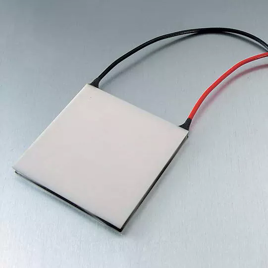
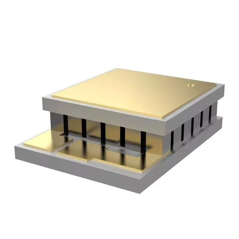
An engineer designing a compact medical analyzer needs to hold a sample chamber at 15°C in a 35°C ambient environment. The enclosure is small, the power budget is limited, and the available space for a cooling system is minimal. The engineer knows that a thermoelectric cooler, or TEC, is the right technology for this application. But which TEC? The answer depends on a number that is often estimated too casually: the required cooling load. If the cooling load is underestimated, the TEC will not hold the setpoint. If it is overestimated, the TEC will be oversized, inefficient, and expensive. Calculating the cooling load correctly is the first step in selecting a thermoelectric cooler that meets the application's requirements without unnecessary cost or complexity.


This guide is written for procurement engineers, design engineers, and buyers who need to specify thermoelectric coolers for cooling applications. We will explain the components of the cooling load, the methods for calculating each component, the role of thermal resistance in the enclosure, the effect of the TEC's coefficient of performance (COP), and the criteria for evaluating a supplier. We will also provide detailed product parameters from our factory at Fuzhou X-Meritan Technology Co., Ltd. Whether you are cooling a medical device, a laser diode, a battery pack, or a compact enclosure, this guide will help you calculate the cooling load accurately and select the right thermoelectric cooler for your application.

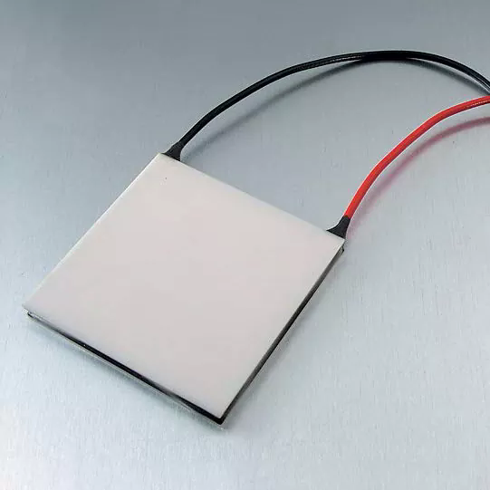
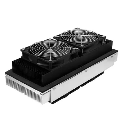
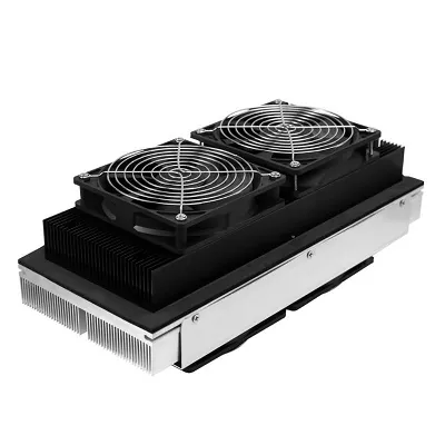
Standard General TE Coolers for Domestic


Table of Contents


1. What Is a Cooling Load and Why Does It Determine TEC Selection?

The cooling load is the total amount of heat that must be removed from the enclosure or the object being cooled to maintain the desired temperature. It is the sum of the active heat load, the passive heat load, and any additional heat sources such as solar radiation or condensation. The cooling load is expressed in watts. For a thermoelectric cooler, the cooling load is the required heat pumping capacity (Qc) at the specific operating conditions. The TEC must be selected so that its Qc at the actual ambient temperature and setpoint is greater than the cooling load, with an appropriate safety margin. If the TEC's Qc is less than the cooling load, the enclosure will not reach the setpoint. If the TEC's Qc is much greater than the cooling load, the TEC will be oversized and will operate at a lower efficiency.

The cooling load calculation is the foundation of TEC selection because it determines the required Qc, which in turn determines the TEC's size, power consumption, and cost. A small medical device may have a cooling load of 10 W, requiring a compact TEC. A battery thermal management system may have a cooling load of 200 W, requiring a larger TEC or an array of TECs. The table below summarizes the three main components of the cooling load and their typical sources.

Component Source Typical Magnitude
Active Heat Load Electronic components, sensors, motors, lasers 1 W to 200 W
Passive Heat Load Conduction through enclosure walls, convection, radiation 5 W to 50 W
Additional Heat Sources Solar radiation, condensation, external heat sources Variable
Total Cooling Load Sum of all components Determines TEC Qc requirement

At Fuzhou X-Meritan Technology Co., Ltd., our factory designs and manufactures thermoelectric coolers for a wide range of cooling applications. We work with our customers to verify that the cooling load calculation is accurate before selecting the TEC. Our engineering team can assist with the calculation and provide guidance on the appropriate safety margin for each application.


2. How Do You Calculate the Active Heat Load?

The active heat load is the heat generated by the components inside the enclosure that are powered by electricity. These components may include electronic circuits, sensors, motors, lasers, LED lights, and any other device that converts electrical energy into heat. The active heat load is calculated by summing the power consumption of all the components that are operating inside the enclosure. For a component that is not 100% efficient, the heat generated is equal to the power input minus the useful work output. In most electronic systems, almost all the electrical power is converted into heat, so the active heat load is approximately equal to the total power consumption. The table below provides a worksheet for calculating the active heat load.

Component Power Consumption (W) Heat Dissipation (W) Notes
Controller Board 5 W 5 W All power dissipated as heat
Sensor Module 2 W 2 W Continuous operation
Laser Diode 3 W 2.5 W 0.5 W emitted as light
Display 1 W 0.8 W 0.2 W emitted as light
Total Active Heat Load 11 W 10.3 W Used for TEC selection

At our factory, we provide thermoelectric coolers with a range of cooling capacities to suit different active heat loads. Our engineering team can review the component list and verify the active heat load calculation. We also recommend that our customers consider the duty cycle of the components, since intermittent operation may reduce the average heat load.


3. How Do You Calculate the Passive Heat Load Through the Enclosure?

The passive heat load is the heat that enters the enclosure from the outside environment through the walls, the lid, and any openings. It is driven by the temperature difference between the ambient environment and the enclosure interior. The passive heat load is calculated using the formula Q = U × A × ΔT, where U is the overall heat transfer coefficient of the enclosure, A is the surface area of the enclosure, and ΔT is the temperature difference between the ambient and the interior. The overall heat transfer coefficient depends on the wall material, the insulation, and the convection conditions on both sides of the wall. For a well-insulated enclosure, U may be as low as 0.5 W/m²K. For an uninsulated enclosure, U may be as high as 5 W/m²K. The table below provides a worksheet for calculating the passive heat load.

Parameter Symbol Value Unit
Overall Heat Transfer Coefficient U 2.0 W/m²K
Surface Area A 0.5 m²
Temperature Difference ΔT 20 (35°C ambient, 15°C interior) K
Passive Heat Load Q 20 W

At X-Meritan, we help our customers calculate the passive heat load by providing the thermal resistance values for our enclosure materials and insulation options. We also advise on the use of reflective coatings and thermal breaks to reduce the passive heat load. Our goal is to ensure that the total cooling load is calculated accurately, so that the selected thermoelectric cooler is neither undersized nor oversized.


4. How Do You Account for Thermal Resistance and Interface Losses?

The cooling load calculation is not complete until the thermal resistance of the interfaces between the TEC and the object being cooled is accounted for. The TEC does not cool the object directly; it cools the cold-side heat sink, which then cools the object through conduction, convection, or radiation. Each interface introduces a thermal resistance that reduces the effective cooling capacity. The most common interface losses are the thermal resistance of the thermal interface material (TIM) between the TEC and the heat sink, the thermal resistance of the heat sink itself, and the thermal resistance of the thermal path from the cold-side heat sink to the object. The table below summarizes the typical thermal resistance values for common interface materials.

Interface Typical Thermal Resistance Notes
Thermal Grease (TEC to Heat Sink) 0.1 - 0.5 °C/W Depends on thickness and contact pressure
Thermal Pad (TEC to Heat Sink) 0.5 - 2.0 °C/W Easier to apply but higher resistance
Heat Sink (Natural Convection) 1.0 - 5.0 °C/W Depends on size and fin design
Heat Sink (Forced Air) 0.2 - 1.0 °C/W Requires fan, but lower resistance
Thermal Path to Object 0.5 - 3.0 °C/W Depends on material and geometry

At our factory, we provide thermoelectric coolers with surface finishes that are optimized for thermal contact. We also offer thermal interface materials and heat sink design support to help our customers minimize interface losses. Our goal is to ensure that the TEC's cooling capacity is transferred efficiently to the object being cooled, so that the system meets its thermal performance requirements.


5. Why Does the Coefficient of Performance Affect the Final TEC Choice?

The coefficient of performance (COP) is the ratio of the cooling capacity (Qc) to the electrical power input (Pin). A higher COP means that the TEC is more efficient, consuming less electrical power for the same cooling capacity. The COP of a thermoelectric cooler depends on the temperature difference between the hot and cold sides, the TEC material, and the operating current. As the temperature difference increases, the COP decreases. This means that a TEC that is selected for a high temperature difference will require more power and will generate more heat, which must be dissipated by the hot-side heat sink. The table below shows the typical COP values for a thermoelectric cooler at different temperature differences.

Temperature Difference (ΔT) Typical COP Implication for TEC Selection
10 K 1.5 - 2.0 High efficiency, low power consumption
20 K 0.8 - 1.2 Moderate efficiency
30 K 0.5 - 0.8 Lower efficiency, higher power consumption
40 K 0.3 - 0.5 Low efficiency, significant heat rejection
50 K 0.2 - 0.3 Very low efficiency, may require multi-stage TEC

At X-Meritan, we provide the COP curves for our thermoelectric coolers, so that our customers can select the TEC that operates at the optimal efficiency for their temperature difference. We also advise on the use of multi-stage TECs for applications that require a large temperature difference. Our goal is to help our customers achieve the required cooling performance with the lowest possible power consumption.


6. How Do You Evaluate a Thermoelectric Cooler Supplier?

Evaluating a supplier of thermoelectric coolers requires a focus on manufacturing capability, performance data, quality control, and technical support. The supplier must have the capability to manufacture TECs to the required specifications, including the correct dimensions, the correct number of couples, and the correct thermal performance. They must provide complete performance data, including the Qc, the COP, the maximum current, and the maximum voltage at different temperature differences. They must have a quality control system that ensures consistent performance from unit to unit. And they must provide technical support to help customers with the cooling load calculation and the TEC selection. The table below summarizes these evaluation criteria.

Evaluation Criterion What to Look For Why It Matters
Manufacturing Capability Precision assembly, testing equipment Ensures product quality and consistency
Performance Data Qc, COP, Imax, Vmax at different ΔT Enables accurate selection
Quality Control ISO 9001, 100% testing Ensures consistent performance
Technical Support Cooling load calculation, TEC selection Helps select the right product
Reliability MTBF data, lifetime testing Ensures long-term performance

At our factory, we have been producing thermoelectric coolers for over a decade. We use precision assembly and testing equipment to ensure that every TEC meets its specifications. We provide complete performance data, including Qc, COP, and maximum ratings. We are ISO 9001 certified, and we perform 100% testing on every unit. Our technical team is available to assist with the cooling load calculation and the TEC selection. We invite you to evaluate us against these criteria and to consider us as your partner for thermoelectric coolers.


7. What Are the Key Product Parameters from Our Factory?

The following table provides the key product parameters for our thermoelectric coolers. These TECs are suitable for a wide range of cooling applications, including medical devices, laser diodes, battery packs, and compact enclosures. Our factory can also produce custom TECs to meet specific requirements.

Parameter Specification Range Notes
Cooling Capacity (Qc) 5 W - 200 W At specified ΔT and current
Maximum Current (Imax) 2 A - 15 A Depends on model
Maximum Voltage (Vmax) 5 V - 24 V Depends on model
Maximum Temperature Difference (ΔTmax) 65 K - 75 K At Imax, in vacuum
COP Range 0.2 - 2.0 Depends on ΔT
Dimensions 15 x 15 mm to 62 x 62 mm Custom sizes available
Number of Couples 31 - 241 Determines cooling capacity
Operating Temperature -40°C to +80°C Depends on solder and sealing
MOQ 10 pieces Negotiable for large orders
Lead Time 2 - 4 weeks Depends on quantity and customization

At our factory, we manufacture our thermoelectric coolers to meet these specifications and more. We can customize the cooling capacity, dimensions, and operating temperature to suit your specific requirements. Our quality control system includes inspection of raw materials, in-process inspection, and 100% final testing before shipment. Our goal is to provide our customers with high-quality thermoelectric coolers that meet their thermal performance requirements.


8. Frequently Asked Questions (FAQ)

Question 1: What is the difference between active and passive heat load?

Answer: Active heat load is the heat generated by the electrical components inside the enclosure, such as controllers, sensors, and lasers. Passive heat load is the heat that enters the enclosure from the outside environment through the walls, lid, and openings. Both must be included in the cooling load calculation. For most compact electronic enclosures, the active heat load is the dominant component. For large enclosures with poor insulation, the passive heat load may be significant.

Question 2: How much safety margin should I add to the cooling load calculation?

Answer: A safety margin of 20% to 30% is typically recommended. This margin accounts for uncertainties in the component power consumption, the thermal resistance of the interfaces, and the aging of the TEC. For critical applications, such as medical devices or laser systems, a larger margin of 50% may be appropriate. At Fuzhou X-Meritan Technology Co., Ltd., we can help you determine the appropriate safety margin for your specific application.

Question 3: Why does the COP decrease as the temperature difference increases?

Answer: The COP decreases as the temperature difference increases because the TEC must work harder to pump heat against a larger temperature gradient. The electrical power input increases, and the cooling capacity decreases, so the ratio of cooling to power decreases. This is why the TEC should be selected for the actual operating temperature difference, not for the maximum ΔT rating. Our factory provides COP curves that show the efficiency at different temperature differences.

Question 4: Can I use a single-stage TEC for a large temperature difference?

Answer: A single-stage TEC can achieve a maximum temperature difference of about 65-75 K. For larger temperature differences, a multi-stage TEC is required. Multi-stage TECs stack two or more stages to achieve a larger total temperature difference, but they are less efficient and more expensive than single-stage TECs. If your application requires a temperature difference greater than 70 K, consult with our engineering team to determine the best solution.

Question 5: How do I calculate the thermal resistance of my heat sink?

Answer: The thermal resistance of a heat sink depends on its geometry, the material, and the airflow conditions. It is typically specified by the heat sink manufacturer in °C/W. For natural convection, the thermal resistance is higher than for forced air. For a rough estimate, a natural convection heat sink with a surface area of 0.1 m² may have a thermal resistance of about 3-5 °C/W. For accurate results, use the manufacturer's data or perform a thermal test. At our factory, we can help you select a heat sink that matches the TEC's thermal requirements.


9. Conclusion

Calculating the required cooling load is the first and most important step in selecting a thermoelectric cooler. The cooling load is the sum of the active heat load, the passive heat load, and any additional heat sources. It must be calculated with care, including the thermal resistance of the interfaces and the effect of the coefficient of performance. By following the calculation methods described in this article, engineers can select a TEC that meets the application's thermal requirements without unnecessary cost or complexity. At Fuzhou X-Meritan Technology Co., Ltd., our factory has the expertise and the products to support your thermoelectric cooling requirements. We provide complete performance data, technical support, and custom designs to help you achieve the best thermal solution.

Whether you are cooling a medical analyzer, a laser diode, a battery pack, or a compact enclosure, we invite you to contact us to discuss your requirements. We can provide samples, technical data, and application support. Our commitment to quality and customer satisfaction has made us a trusted partner for thermal management solutions around the world.

Contact Fuzhou X-Meritan Technology Co., Ltd. today to discuss your thermoelectric cooler requirements and discover how our products can meet your cooling load needs.

Related News
Leave me a message
X
We use cookies to offer you a better browsing experience, analyze site traffic and personalize content. By using this site, you agree to our use of cookies. Privacy Policy
RejectAccept